عدد المساهمات : 2461نقاط : 4249السٌّمعَة : 9الجنس : علم بلدك : تاريخ الميلاد : 03/04/1950تاريخ التسجيل : 30/07/2012العمر : 74 الموقع : السودان - سنارالعمل/الترفيه : طبيب عمومى وموجات صوتيةالساعة الان : دعائي :
موضوع: Ultrasound Physics Scanning AND Modes M Mode الجمعة أبريل 19, 2024 8:26 pm
عدل سابقا من قبل د.كمال سيد في الأحد أبريل 21, 2024 12:21 pm عدل 1 مرات
د.كمال سيد Admin
عدد المساهمات : 2461نقاط : 4249السٌّمعَة : 9الجنس : علم بلدك : تاريخ الميلاد : 03/04/1950تاريخ التسجيل : 30/07/2012العمر : 74 الموقع : السودان - سنارالعمل/الترفيه : طبيب عمومى وموجات صوتيةالساعة الان : دعائي :
موضوع: رد: Ultrasound Physics Scanning AND Modes M Mode الجمعة أبريل 19, 2024 8:27 pm
د.كمال سيد Admin
عدد المساهمات : 2461نقاط : 4249السٌّمعَة : 9الجنس : علم بلدك : تاريخ الميلاد : 03/04/1950تاريخ التسجيل : 30/07/2012العمر : 74 الموقع : السودان - سنارالعمل/الترفيه : طبيب عمومى وموجات صوتيةالساعة الان : دعائي :
موضوع: رد: Ultrasound Physics Scanning AND Modes M Mode الجمعة أبريل 19, 2024 8:28 pm
د.كمال سيد Admin
عدد المساهمات : 2461نقاط : 4249السٌّمعَة : 9الجنس : علم بلدك : تاريخ الميلاد : 03/04/1950تاريخ التسجيل : 30/07/2012العمر : 74 الموقع : السودان - سنارالعمل/الترفيه : طبيب عمومى وموجات صوتيةالساعة الان : دعائي :
موضوع: رد: Ultrasound Physics Scanning AND Modes M Mode الجمعة أبريل 19, 2024 8:29 pm
د.كمال سيد Admin
عدد المساهمات : 2461نقاط : 4249السٌّمعَة : 9الجنس : علم بلدك : تاريخ الميلاد : 03/04/1950تاريخ التسجيل : 30/07/2012العمر : 74 الموقع : السودان - سنارالعمل/الترفيه : طبيب عمومى وموجات صوتيةالساعة الان : دعائي :
موضوع: رد: Ultrasound Physics Scanning AND Modes M Mode السبت أبريل 20, 2024 7:45 pm
د.كمال سيد Admin
عدد المساهمات : 2461نقاط : 4249السٌّمعَة : 9الجنس : علم بلدك : تاريخ الميلاد : 03/04/1950تاريخ التسجيل : 30/07/2012العمر : 74 الموقع : السودان - سنارالعمل/الترفيه : طبيب عمومى وموجات صوتيةالساعة الان : دعائي :
موضوع: رد: Ultrasound Physics Scanning AND Modes M Mode السبت أبريل 20, 2024 7:52 pm
د.كمال سيد Admin
عدد المساهمات : 2461نقاط : 4249السٌّمعَة : 9الجنس : علم بلدك : تاريخ الميلاد : 03/04/1950تاريخ التسجيل : 30/07/2012العمر : 74 الموقع : السودان - سنارالعمل/الترفيه : طبيب عمومى وموجات صوتيةالساعة الان : دعائي :
موضوع: رد: Ultrasound Physics Scanning AND Modes M Mode الأحد أبريل 21, 2024 12:22 pm
The Principles of Ultrasound Imaging
د.كمال سيد Admin
عدد المساهمات : 2461نقاط : 4249السٌّمعَة : 9الجنس : علم بلدك : تاريخ الميلاد : 03/04/1950تاريخ التسجيل : 30/07/2012العمر : 74 الموقع : السودان - سنارالعمل/الترفيه : طبيب عمومى وموجات صوتيةالساعة الان : دعائي :
موضوع: Ultrasound and imaging الإثنين مايو 06, 2024 5:26 pm
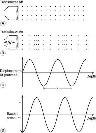
Ultrasound and imaging It is important to understand how ultrasound interacts with tissue to be able to interpret ultrasound images and to identify artifacts. Knowledge of how an image is produced allows optimal use of the scanner controls. The aim of this and the next two chapters is to give a simple explanation of the process involved in producing images and blood flow measurements. NATURE OF ULTRASOUND Ultrasound, as the name implies, 1/ is high-frequency sound. 2/ Sound waves travel through a medium by causing local displacement of particles within the medium; however, 3/ there is no overall movement of the medium. Unlike light, 4/ sound cannot travel through a vacuum as (sound waves need a supporting medium). Consider a piece of string held at both ends: with one end briefly shaken, the vibration caused will travel along the string and in so doing transmit energy from one end of the string to the other. This is known as a transverse wave, as the movement of the string is at right angles to the direction in which the wave has moved.5/ Ultrasound is a longitudinal wave, as the displacement of the particles within the medium is in the same direction as that in which the wave is travelling. Figure 2.1 shows a medium with particles distributed evenly within it. The position of the particles within the medium will change as a sound wave passes through it, causing local periodic displacement of these particles (Fig. 2.1B). The size, or amplitude, of these displacements is shown in Figure 2.1C. 6/ As the particles move within the medium, local increases (compression) and decreases (rarefaction) in pressure are generated (Fig. 2.1D). Figure 2.1 (A) A medium consisting of evenly distributed particles. (B) The positions of the particles change (shown here at a given point in time) as the ultrasound wave passes through the medium. (C) The amplitude of the particle displacement. (D) Excess pressure.
Wavelength and frequency
Ultrasound is usually described by its frequency, which is related to the length of the wave produced. The wavelength of a sound wave is the distance between consecutive points where the size and direction of the displacement are identical and the direction in which the particles are travelling is the same. The wavelength is represented by the symbol λ and is shown in Figure 2.1C. The time taken for the wave to move forwards through the medium by one wavelength is known as the period (τ). The frequency, f, is the number of cycles of displacements passing through a point in the medium during 1 second (s) and is given by: (2.1) The unit of frequency is the hertz (Hz), with 1 Hz being one complete cycle per second. Audible sound waves are in the range of 20 Hz to 20 kHz, whereas medical ultrasound scanners typically use high frequencies of between 2 and 15 MHz (i.e., between 2 000 000 and 15 000 000 Hz).
Speed of ultrasound
Sound travels through different media at different speeds (e.g., sound travels faster through water than it does through air). The speed of a sound wave, c, is given by the distance traveled by the disturbance during a given time and is constant in any specific material. The speed can be found by multiplying the frequency by the wavelength and is usually measured in meters per second (m/s):
(2.2)
The speed of sound through a material depends both on the density and the compressibility of the material. The more dense and the more compressible the material, the slower the wave will travel through it. The speed of sound is different for the various tissues in the body (Table 2.1). Knowledge of the speed of sound is needed to determine how far an ultrasound wave has traveled. This is required in both imaging and pulsed Doppler (as will be seen later), but ultrasound systems usually make an estimate by assuming that the speed of sound is the same in all tissues: 1540 m/s. This can lead to small errors in the estimated distance traveled because of the variations in the speed of sound in different tissues. https://radiologykey.com/ultrasound-and-imaging/ next
د.كمال سيد Admin
عدد المساهمات : 2461نقاط : 4249السٌّمعَة : 9الجنس : علم بلدك : تاريخ الميلاد : 03/04/1950تاريخ التسجيل : 30/07/2012العمر : 74 الموقع : السودان - سنارالعمل/الترفيه : طبيب عمومى وموجات صوتيةالساعة الان : دعائي :
موضوع: Speed of ultrasound الإثنين مايو 06, 2024 6:14 pm
Speed of ultrasound
Sound 1/ travels through different media at different speeds (e.g., sound travels faster through water than it does through air). 2/ The speed of a sound wave, c, is given by the distance traveled by the disturbance during a given time and is constant in any specific material. The speed can be found by multiplying the frequency by the wavelength and is usually measured in meters per second (m/s):
(2.2) The 3/speed of sound through a material depends both on the density and the compressibility of the material. The more dense and the more compressible the material, the slower the wave will travel through it. The 4/ speed of sound is different for the various tissues in the body (Table 2.1). Knowledge of the speed of sound is needed to determine how far an ultrasound wave has traveled. This is required in both imaging and pulsed Doppler (as will be seen later), but ultrasound systems usually make an estimate by 5/ assuming that the speed of sound is the same in all tissues: 1540 m/s. This can lead to small errors in the estimated distance traveled because of the variations in the speed of sound in different tissues. GENERATION OF ULTRASOUND WAVES The 1/ term ‘transducer’ simply means a device that converts one form of energy into another. In the case of an ultrasound transducer, 2/ (this conversion is from electrical energy to mechanical vibration). The 3/ piezoelectric effect is the method by which most medical ultrasound is generated. (Piezoelectric materials will vibrate mechanically when a varying voltage is applied across them). The 4/ frequency of the voltage applied will affect the frequency with which the material vibrates. The 5/ thickness of the piezoelectric element will determine the frequency at which the element will vibrate most efficiently; this is known as the (resonant frequency of the transducer). The 6/speed of sound within the element will depend on the material from which it is made. A 7/ resonant frequency occurs when the thickness of the element is half the wavelength of the sound wave generated within it. At this frequency, the reflected waves from the front and back faces of the element act to reinforce each other, so increasing the size of the vibration produced. 8/ When an appropriate coupling medium is used (e.g., ultrasound gel), this vibration will be transmitted into a surrounding medium, such as the body. 9/ The named frequency of a transducer is its resonant frequency. This is not to say that the transducer will not function at a different frequency, but it will be much less efficient at those frequencies. Most modern imaging transducers are designed as broad-band transducers, meaning that they will function efficiently over a wide range of frequencies, and these are usually labeled with the frequency range over which they operate (e.g., 3–9 MHz). Figure 2.2 shows how the transducer output of narrow-band and broad-band transducers varies with the frequency of the excitation voltage. A broad-band transducer is more efficient over a wider range of frequencies than a narrow-band transducer.10/ Ultrasound transducers also use the piezoelectric effect to convert the returning ultrasound vibrations back into electrical signals. These 11/ signals can then be amplified, analyzed, and displayed to provide anatomical images together with flow information. Figure 2.2 Plot of transducer output versus frequency for a broad-band and a narrow-band transducer. A broad-band transducer will be more efficient over a wider range of frequencies than a narrow-band transducer. https://radiologykey.com/ultrasound-and-imaging/
د.كمال سيد Admin
عدد المساهمات : 2461نقاط : 4249السٌّمعَة : 9الجنس : علم بلدك : تاريخ الميلاد : 03/04/1950تاريخ التسجيل : 30/07/2012العمر : 74 الموقع : السودان - سنارالعمل/الترفيه : طبيب عمومى وموجات صوتيةالساعة الان : دعائي :
موضوع: Pulsed US الإثنين مايو 06, 2024 6:40 pm
Pulsed ultrasound
Simple Doppler systems operate with a continuous single-frequency excitation voltage, but all imaging systems and pulsed Doppler systems use pulsed excitation signals. If ultrasound is continuously transmitted along a particular path, the energy will also be continuously reflected back from any boundary in the path of the beam, and it will not be possible to predict where the returning echoes have come from. However, when a pulse of ultrasound is transmitted it is possible to predict the distance (d) of a reflecting surface from the transducer if the time (t) between transmission and reception of the pulse is measured and the velocity (c) of the ultrasound along the path is known, as follows: (2.3) The factor 2 arises from the fact that the pulse travels along the path twice, once on transmission and once on its return (Go Return Time). This can be used to predict where returning echoes have originated from within the body.
Frequency content of pulses
Typically, 1/ the pulses used in imaging ultrasound are very short and will only contain 1–3 cycles in order that reflections from boundaries that are close together can be easily separated. Pulsed Doppler signals are 2/longer and contain several cycles. 3/ In fact, a pulse is made up not of a single frequency but of a range of frequencies of different amplitudes. Different-shaped pulses will have different frequency contents. Figure 2.3 illustrates how a signal can be made up of the sum of several different frequencies. The 4/frequency content of a signal can be displayed on a graph, such as those shown in Figure 2.4 (right panels). This is known as a frequency spectrum and displays the frequencies present within the signal against the relative amplitudes of these frequencies.Figure 2.4A provides an example of a continuous signal consisting of a single frequency. As only one frequency is present in the signal, the frequency spectrum displays a single line at that frequency (Fig. 2.4B). Figure 2.4C, E, and G give examples of three differently shaped signals along with their frequency spectra (Fig. 2.4D, F, and H), showing the range of frequencies present in each of the different signals. As ultrasound imaging uses pulsed ultrasound, the transducer is not transmitting a single frequency but a range of frequencies. Figure 2.3 A signal is made up of, or can be broken down into, sine waves of different frequencies, different amplitudes and phases.
(From Fish 1990, with permission.) Figure 2.4 Four different signals (amplitude plotted against time) and their corresponding frequency spectra (power plotted against frequency). (A, B) For a continuous single frequency. (C, D) Signal shown in Figure 2.3. (E, F) A long pulse. (G, H) A short pulse. The shorter the pulse, the greater the range of frequencies within the pulse
Beam shape
The shape of the ultrasound beam produced by a transducer will depend on 1/ the shape of the element(s), on the 2/ transmitted frequency, and on whether 3/ the beam is focused. The shape of the beam will affect the region of tissue that will be insonated and from which returning echoes will be received. Multi-element array transducers use several elements to produce the beam, as discussed later in this chapter. https://radiologykey.com/ultrasound-and-imaging/
د.كمال سيد Admin
عدد المساهمات : 2461نقاط : 4249السٌّمعَة : 9الجنس : علم بلدك : تاريخ الميلاد : 03/04/1950تاريخ التسجيل : 30/07/2012العمر : 74 الموقع : السودان - سنارالعمل/الترفيه : طبيب عمومى وموجات صوتيةالساعة الان : دعائي :
موضوع: interaction of US with surfaces الإثنين مايو 06, 2024 8:04 pm
INTERACTION OF ULTRASOUND WITH SURFACES The 1/ creation of an ultrasound image depends on the way in which ultrasound energy interacts with the tissue as it passes through the body. When an ultrasound wave 2/ meets a large smooth interface between two different media, some of the energy will be reflected back, and this is known as specular reflection. The relative 3/ proportions of the energy reflected and transmitted depend on the change in the acoustic impedance between the two materials (Fig. 2.5). The acoustic impedance of a medium is the impedance (similar to resistance) the material offers against the passage of the sound wave through it and depends on the density and compressibility of the medium. The greater the change in the acoustic impedance across a boundary, the greater the proportion of the ultrasound that is reflected. There is, for example, a large difference in acoustic impedance between soft tissue and bone, or between soft tissue and air, and such interfaces will produce large reflections. This is the reason why ultrasound cannot be used to image beyond lung or bone, except in limited situations, as only a small proportion of the ultrasound is transmitted. It is also the reason for the loss of both imaging and Doppler information beyond calcified arterial walls, bone (Fig. 10.13), and bowel gas, leading to an acoustic shadow beyond. Table 2.2 shows the ratio of the reflected to incident wave amplitude for a range of reflecting interfaces. Figure 2.5 When the ultrasound beam meets a boundary between two media, some of the ultrasound will be transmitted and some will be reflected. (A) When the two media have similar acoustic impedances, the majority of the ultrasound will be transmitted across the boundary. (B) When the two media have different acoustic impedances, most of the ultrasound will be reflected. Table 2.2 The ratio of reflected to incident wave amplitude for an ultrasound beam perpendicular to different reflecting interfaces The path along which the reflected ultrasound travels will also affect the amplitude of the signal detected by the transducer. 1/ If the beam is perpendicular to the interface, the reflected ultrasound will travel back along the same path to the transducer. 2/ If, however, the beam intercepts the interface at an angle of less than 90°, then the beam will be reflected along a different path. Figure 2.6 shows that the angle of incidence (θi) is the same as the angle of reflection (θr https://radiologykey.com/ultrasound-and-imaging/
د.كمال سيد Admin
عدد المساهمات : 2461نقاط : 4249السٌّمعَة : 9الجنس : علم بلدك : تاريخ الميلاد : 03/04/1950تاريخ التسجيل : 30/07/2012العمر : 74 الموقع : السودان - سنارالعمل/الترفيه : طبيب عمومى وموجات صوتيةالساعة الان : دعائي :
موضوع: Interactions of US with Tissues الثلاثاء مايو 07, 2024 1:16 pm
Interactions of Ultrasound with Tissues Interactions of ultrasound are chiefly based 1/ on the acoustic impedance of tissues and result 2/ in reflection, refraction, scattering, and absorption of the ultrasound energy. Imaging systems using ultrasound have attained a large presence as point-of-care (PoC) devices across many clinical domains over the past 10 years. The success of ultrasound for this purpose is attributed to several characteristics, including 1/ the low cost and and 2/ portability of ultrasound devices, 3/ the nonionizing nature of ultrasound waves, and the 4/ ability to produce real-time images of the acoustic properties of the tissues and tissue structures in the body to deliver timely patient care, among many positive attributes. An understanding of the basic physics of ultrasound, in addition to hands-on training, practice, and development of experience are of great importance in its effective and safe use. This chapter describes the characteristics, properties, and production of ultrasound; interaction with tissues, acquisition, processing, and display of the ultrasound image; the instrumentation; achievable measurements, including blood velocity; and safety issues.
Characteristics of Sound
Sound is1/ mechanical energy that propagates through a continuous, elastic medium by the compression (high pressure) and rarefaction (low pressure) of particles that comprise it. ((Compression is caused by a mechanical inward deformation by an external force, such as an expanding and contracting transducer crystal composed of multiple elements in contact with the medium)). 2/ During transducer surface expansion, A) an increase in the local pressure at contact occurs. B) Contraction of the crystal follows, C) causing a decrease in pressure. The mechanical 3/ energy imparted at the surface is transferred to adjacent particles of the medium, which travels at the speed of sound through the medium. 4/ Continuous expansion and contraction of the crystal surface by an external power source introduces energy into the medium as a series of compressions and rarefactions, traveling as a wave front in the direction of travel, known as a longitudinal wave, as shown in Fig. 1.1 .
Fig. 1.1 Mechanical energy is generated from an expanding and contracting crystal in contact with a medium, introducing high-pressure (compression) and low-pressure (rarefaction) variations of the constituent particles that transfer the energy to adjacent particles as a longitudinal wave.
Wavelength, Frequency, Speed
The wavelength ( λ ) is the distance between any two repeating points on the wave (a cycle), typically measured in millimeters (mm). The frequency ( f ) is the number of times the wave repeats per second (s), also defined in hertz (Hz), where 1 Hz = 1 cycle/s. Frequency identifies the category of sound : less than 15 Hz is infrasound, 15 Hz to 20,000 Hz (20 kHz) is audible sound, and above 20 kHz is ultrasound. Medical ultrasound typically uses frequencies in the million cycles/ s megahertz (MHz) range, from 1 to 15 MHz, with some specialized ultrasound applications beyond 50 MHz. The period is the time duration of one wave cycle and is equal to 1/ f . The speed of sound, c, is the distance traveled per unit time through a medium and is equal to the wavelength (distance) divided by the period (time). As frequency is inversely equal to the period, the product of wavelength and frequency is equal to the speed of sound,c = λ f. The speed of sound varies substantially for different materials, based 1/ on compressibility, 2/stiffness, and 3/ density characteristics of the medium. For instance, air is highly compressible and of low density, with a relatively low speed of sound; bone is stiff and dense, with a relatively very high speed of sound; and soft tissues have compressibility and density characteristics with intermediate speeds, as listed in Table 1.1 . Of importance are the 4/ average speeds for “soft tissue” (1540 m/s), fatty tissue (1450 m/s), and air (330 m/s). To relate time with depth interactions in the patient, medical ultrasound devices assume a speed of sound of 1540 m/s, despite slight differences in actual speed for the various tissues encountered. Changes in the speed of sound can affect how ultrasound travels through the tissues and may result in unexpected artifacts (see Chapter 2 on speed artifact and refraction artifact). 5/ The product of the density and speed of sound is known as the acoustic impedance . This characteristic of the tissues is intrinsic in the generation of ultrasound echoes, which return to the transducer to create the ultrasound image. More detail is in the next section on ultrasound interactions. Acoustic impedance is the product of density and speed of sound. The rayl is the named unit, with base units of kg/m 2 /s. Acoustic impedance directly relates to the propagation characteristics of ultrasound in a given medium and between media. https://radiologykey.com/physics-of-ultrasound-3/
د.كمال سيد Admin
عدد المساهمات : 2461نقاط : 4249السٌّمعَة : 9الجنس : علم بلدك : تاريخ الميلاد : 03/04/1950تاريخ التسجيل : 30/07/2012العمر : 74 الموقع : السودان - سنارالعمل/الترفيه : طبيب عمومى وموجات صوتيةالساعة الان : دعائي :
موضوع: Interactions of US with Tissues الثلاثاء مايو 07, 2024 2:02 pm
In a homogeneous medium, ultrasound frequency and speed of sound are constant. When higher ultrasound frequency is selected, the wavelength becomes shorter, giving better detail and spatial resolution along the direction of propagation. For instance, in soft tissue with a speed of 1540 m/s, a 5-MHz frequency has a wavelength in tissue of λ = c / f ; 1540 m/s ÷ 5,000,000/s = 0.00031 m = 0.31 mm. A 10-MHz frequency has a wavelength = 0.15 mm ( Fig. 1.2 ). Although higher frequencies provide 1/ better resolution, they are also 2/ more readily attenuated, and depth 3/ penetration can be inadequate for certain examinations, such as for the heart and abdomen. Fig. 1.2 Wavelength and frequency are inversely proportional, determined by the speed of sound in the medium. For soft tissue, with an average speed of 1540 m/s, the wavelength is directly calculated as the speed of sound divided by the frequency in cycles/s. As frequency remains constant in different media, wavelength must change. Shown is the wavelength for a 5-MHz frequency in fat (red line), with a speed of sound of 1450 m/s.
Intensity
The amount of ultrasound energy imparted to the medium is dependent on the pressure amplitude variations generated by the degree of transducer expansion and contraction, controlled by the transmit gain applied to a transducer. Power is the amount of energy per unit time introduced into the medium, measured in milliwatts (mW). Intensity is the concentration of the power per unit area in the ultrasound beam, typically expressed in mW/cm 2 . Signals used for creating images are derived from ultrasound interactions in the tissues and the returning intensity of the produced echoes. Absolute intensity depends on the method of ultrasound production and can result in heating or mechanical disruption of tissues, as discussed later in this chapter.
Interactions of Ultrasound with Tissues
Interactions of ultrasound are chiefly based on the acoustic impedance of tissues and result in reflection, refraction, scattering, and absorption of the ultrasound energy.
Acoustic Impedance
Acoustic impedance , Z, is a measure of tissue stiffness and flexibility, equal to the product of the density and speed of sound: Z = ρ c, where ρ is the density in kg/m 3 and c is the speed of sound in m/s, with the combined units given the name rayl, where 1 rayl is equal to 1 kg/(m 2 s). Air, soft tissues, and bone represent the typical low, medium, and high ranges of acoustic impedance values encountered in the patient, as listed in Table 1.1 . The efficiency of sound energy transfer from one tissue to another is largely based on the differences in acoustic impedance—if impedances are similar, a large fraction of the incident intensity at the boundary interface will be transmitted, and if the impedances are largely different, most will be reflected. In most soft tissues, these differences are typically small, allowing for ultrasound travel to large depths in the patient. https://radiologykey.com/physics-of-ultrasound-3/
د.كمال سيد Admin
عدد المساهمات : 2461نقاط : 4249السٌّمعَة : 9الجنس : علم بلدك : تاريخ الميلاد : 03/04/1950تاريخ التسجيل : 30/07/2012العمر : 74 الموقع : السودان - سنارالعمل/الترفيه : طبيب عمومى وموجات صوتيةالساعة الان : دعائي :
موضوع: Reflection & Refraction الثلاثاء مايو 07, 2024 4:21 pm
Reflection
Reflection occurs when a beam is traveling perpendicular (at normal incidence or 90 degrees) to the boundary between two tissues that have a difference in acoustic impedance ( Fig. 1.3A ). Reflection of a sound wave occurs when the wave passes between two tissues of different acoustic impedances and a fraction of the wave 'bounces' back. This forms one of the major principles of ultrasound imaging as the ultrasound probe detects these reflected waves to form the desired image. Like light and other electromagnetic radiation, the incoming incident wave bounces off the boundary at an angle of incidence (θi), which is equal to the angle of reflection (θr). θi = θr This is in contrast to refraction, where the angles of incidence and refraction may not be equal but are dependent on the difference in tissue acoustic impedance.
Intensity of reflection
The intensity of the reflected wave is described by the reflection coefficient (RI), which is defined as the intensity of the reflected sound wave (Ir) divided by the intensity of the incident sound wave (Ii). RI = Ir / Ii Thus, every tissue interface has its own reflection coefficient (RI). For example the RI,fat→muscle is 0.015 meaning that if an incoming sound wave encountered a fat to muscle boundary, 1.5% of that sound wave would be reflected at that boundary. This would be compared to the RI,muscle→bone which is 0.41 where 41% of the incident sound wave would be reflected.
Transmitted intensity
Due to the conservation of energy law the energy that would be transmitted through the boundary would represent all the energy from the incident sound wave which was not reflected. The transmission coefficient (TI) is thus: TI = 1 − RI The reflection coefficient of the typical muscle to air boundary is almost 99% making almost all the sound waves reflect off this interface. Therefore, almost no sound would make it past the air filled cavity making tissues 'beyond' this undetected by ultrasound. This is the reason gel must be used on transducers to remove any pockets of air.
Phase shift
It should also be noted that if a sound wave travels from a medium of lower acoustic impedence, (lower speed) to higher acoustic impedance (faster speed), the reflected wave undergoes a 180-degree phase shift in amplitude assuming a smooth interface between tissues. Recall that Z (acoustic impedance) = DC (density × speed).
Quiz questions
https://radiopaedia.org/articles/reflection Fig. 1.3 A boundary separating two tissues with different acoustic impedances demonstrates (A) perpendicular (normal) incidence of an ultrasound wave with reflection of an echo back to the source (transducer) and transmission to greater depths in a straight line and (B) incidence of the wave at a nonperpendicular angle, with the incident angle measured relative to the normal incidence and the reflected echo at an angle opposite but equal to the incident angle. The transmitted ultrasound wave is refracted if the speed of sound is different in the two tissues, with the angle of refraction also referenced to the normal direction. Refraction angle depends on the relative speed differences and the change in the wavelength at the boundary. A high fraction of ultrasound intensity is transmitted at tissue boundaries for tissues that have similar acoustic impedance. For tissues with large differences of acoustic impedance, such as air-to-tissue or tissue-to-bone boundaries, most of the intensity is reflected, with no further propagation of the ultrasound pulse. At a muscle–air interface, nearly 100% of incident intensity is reflected, making anatomy unobservable beyond an air-filled cavity. Acoustic coupling gel placed between the transducer and the patient’s skin is a critical part of the standard ultrasound imaging procedure to ensure good transducer coupling and to eliminate air pockets that would reflect the ultrasound. For imaging beyond lung structures, avoidance of the ribs and presence of a “tissue conduit” are necessary to achieve propagation of the pulse. When an ultrasound pulse is incident on a tissue boundary at an angle other than 90 degrees (normal incidence), the reflected ultrasound echo is directed away from the transducer and does not generate a signal. https://radiologykey.com/physics-of-ultrasound-3/
د.كمال سيد Admin
عدد المساهمات : 2461نقاط : 4249السٌّمعَة : 9الجنس : علم بلدك : تاريخ الميلاد : 03/04/1950تاريخ التسجيل : 30/07/2012العمر : 74 الموقع : السودان - سنارالعمل/الترفيه : طبيب عمومى وموجات صوتيةالساعة الان : دعائي :
موضوع: Refraction & Scattering الثلاثاء مايو 07, 2024 6:31 pm
Refraction
Refraction is a change in direction of the transmitted ultrasound pulse when the incident pulse is NOT perpendicular to the tissue boundary and the speeds of sound in the two tissues are different. The frequency does not change, but the ultrasound wavelength changes at the boundary due to the speed change, resulting in a redirection of the transmitted pulse, as shown in Fig. 1.3B . The angle of redirection is dependent on the change in wavelength; no refraction occurs when the speed of sound is the same in the two tissues or with perpendicular incidence. Because a straight-line propagation of the ultrasound pulse is assumed, misplacement of anatomy can result when refraction occurs. See Chapter 2 on ultrasound artifacts for further discussion and manifestation of this type of artifact. Refraction occurs when the incident sound wave contacts the boundary of tissues at an oblique angle. This causes the reflected sound beam to travel in a direction that is away from the transducer (Figure 2.9). Refraction, therefore, results in a loss of the propagated signal. Refraction occurs when the ultrasound beam crosses a boundary between tissues that have different speeds of sound propagation. The sound beam 'bends' from its original path. The appearances generated within the image can be confusing. A classic example of this is the 'disappearing twin' artefact.
Scattering
Scattering arises from objects and interfaces within a tissue that are about the size of the ultrasound wavelength or smaller. At low frequencies (1–5 MHz), wavelengths are relatively large, and tissue boundaries appear smooth or specular (mirror-like). A specular reflector is a smooth boundary between two media. At higher frequencies (5–15 MHz), wavelengths are smaller, and boundaries become less smooth, causing echo reflection in many directions. A nonspecular reflector represents a boundary that presents many different angles to the ultrasound beam, and returning echoes have significantly less intensity ( Fig. 1.4 ). Many organs can be identified by a defined “signature” caused by intrinsic structures that produce variations in the returning scatter intensity. Scatter amplitude differences from one tissue region to another result in corresponding brightness changes on the ultrasound display. In general, the echo signal amplitude from a tissue or material depends on 1/ the number of scatterers per unit volume, 2/ the acoustic impedance differences at interfaces, 3/ the sizes of the scatterers, and 4/ the ultrasound frequency. Higher scatter amplitude tissues are called hyperechoic,and lower scatter amplitude tissues are called hypoechoic relative to the average background signal. Scattered echo signals are more prevalent relative to specular echo signals when using higher ultrasound frequencies. Fig. 1.4 Specular and nonspecular reflection boundaries are chiefly dependent on wavelength of the ultrasound beam and therefore frequency. Higher-frequency operation generates shorter wavelengths that are about the same size as the boundary variations, leading to nonspecular interactions and diffuse reflection patterns. https://radiologykey.com/physics-of-ultrasound-3/
Scattering occurs when a sound wave strikes a structure with a differentacoustic impedance to the surrounding tissue and which is smaller than the =wavelength&lang=us]wavelength of the incident sound wave. Such structures are known as “diffuse reflectors,” with examples being red blood cells and non-smooth surfaces of visceral organs. "Specular reflectors" are tissues with smooth interfaces from which ultrasound waves are reflected in a specular fashion such as vessel wall, muscle fasciae, renal collecting system, diaphragm, and liver capsule. In contrast to “specular reflectors”, “diffuse reflectors” cause ultrasound waves to scatter in all directions thus resulting in multiple echoes propagating from the numerous tiny structures. Not only does this scattering result in echoes with smaller amplitudes (compared to specular reflection) but the scattered echoes also interact with each other. This interaction causes constructive and destructive interference of the waves. The resultant image is termed “speckle” due to the various intensities of the echoes received by the transducer, and this is seen as an irregularity in the greyscale of the image. Speckle artifact may be encountered in ultrasound. It is caused by the scattering of waves from the surface of small structures within a certain tissue. The artifact produces a textured appearance Most echoes from ultrasound imaging arise from scattering, rather than the reflection from specular reflectors. The speckle arising from this scatter results in the grainy appearance of the parenchyma of organs and also the signal in Doppler ultrasound.
عدد المساهمات : 2461نقاط : 4249السٌّمعَة : 9الجنس : علم بلدك : تاريخ الميلاد : 03/04/1950تاريخ التسجيل : 30/07/2012العمر : 74 الموقع : السودان - سنارالعمل/الترفيه : طبيب عمومى وموجات صوتيةالساعة الان : دعائي :
موضوع: Absorption and Attenuation الثلاثاء مايو 07, 2024 7:35 pm
Absorption and Attenuation
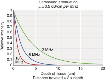
Attenuation is the loss of intensity with distance traveled, caused by scattering and absorption of the incident beam.Scattering has a strong dependence on increasing ultrasound frequency. Absorption occurs by transferring energy to the tissues that result in heating or mechanical disruption of the tissue structure. The combined effects of scattering and absorption result in exponential attenuation of ultrasound intensity with distance travelled as a function of increasing frequency. When expressed in decibels (dB), (a logarithmic measure of intensity), attenuation in dB/cm linearly increases with ultrasound frequency. An approximate rule of thumb for ultrasound attenuation average in soft tissue is 0.5 dB/cm times the frequency in MHz. Compared with a 1-MHz beam, a 2-MHz beam will have approximately twice the attenuation, a 5-MHz beam will have five times the attenuation, and a 10-MHz beam will have ten times the attenuation per unit distance traveled . Therefore higher-frequency ultrasound beams have a rapidly diminishing penetration depth ( Fig. 1.5 ), so careful selection of the transducer frequency must be made in the context of the imaging depth needed. The loss of ultrasound intensity in decibels can be determined empirically for different tissues by measuring as a function of distance travelled in centimeters (cm) and is the attenuation coefficient, μ , expressed in dB/cm . For a given ultrasound frequency, tissues and fluids have widely varying attenuation coefficients chiefly resulting from structural and density differences, as indicated in Table 1.2 for a 1-MHz ultrasound beam. Fig. 1.5 Attenuation and relative intensity of ultrasound remaining as a function of depth for 2-, 5-, and 10-MHz beams https://radiologykey.com/physics-of-ultrasound-3/ Attenuation in ultrasound is the reduction in amplitude of the ultrasound beam as a function of distance through the imaging medium. Accounting for attenuation effects in ultrasound is important because a reduced signal amplitude can affect the quality of the image produced. Whereas absorption relates to the conversion of ultrasonic energy into thermal energy within a medium, attenuation refers to the total propagation losses that result in a reduction of the beam intensity. These losses include those due to (reflection, scattering, refraction, and absorption).
Why does bone attenuate ultrasound? The overall attenuation is the combination of absorption and scattering. Cancellous bone is a porous composite material composed of marrow and trabecular networks. Marrow is a fluid-like viscous medium; the ultrasound energy will be absorbed due to its viscous material properties examples of attenuation :In physics, attenuation (in some contexts, extinction) is the gradual loss of flux intensity through a medium. For instance, dark glasses attenuate sunlight, lead attenuates X-rays, and water and air attenuate both light and sound at variable attenuation rates. When ultrasonic waves are generated and transmitted through the material, energy losses are obvious. With ultrasonic propagation, attenuation occurs due to the effects of scattering, absorption, and the difference in acoustic impedance of two different materials at their interface What Causes attenuation? Noise. Extra noise on networks, like radio frequencies, electrical currents, and wire leakage, may interfere with the signal and cause attenuation. The more noise you have, the more attenuation you experience.
د.كمال سيد Admin
عدد المساهمات : 2461نقاط : 4249السٌّمعَة : 9الجنس : علم بلدك : تاريخ الميلاد : 03/04/1950تاريخ التسجيل : 30/07/2012العمر : 74 الموقع : السودان - سنارالعمل/الترفيه : طبيب عمومى وموجات صوتيةالساعة الان : دعائي :
موضوع: The Ultrasound System الثلاثاء مايو 07, 2024 7:38 pm
The Ultrasound System
PoC ultrasound systems are available from many vendors and come with different features and options, which depend on acquisition capabilities,number of transducer probes, durability, software functionality, size and weight, battery longevity for handheld units, power requirements, and other considerations. Although all ultrasound systems have unique instrumentation, software, and user interfaces, common components include transducer probes, pulser, beam former, scan converter, processor, display, and user interface for instrumentation adjustments and controls.
Ultrasound Transducer Operation and Beam Properties
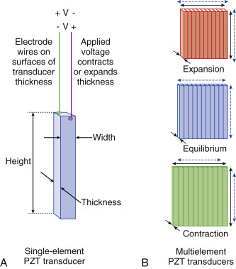
Ultrasound is produced and detected with 1/ a transducer array, composed of hundreds of ceramic elements with electromechanical (piezoelectric) properties. Ultrasound transducers for medical imaging applications employ a synthetic piezoelectric ceramic, Lead–Zirconate–Titanate (PZT), with a crystal structure that generates a surface charge of either negative or positive polarity when its thickness is expanded under negative pressure or compressed under positive pressure due to the internal molecular crystal polarity. 2/Surface electrodes and wires are attached to each element and 3/ multiplexed to a transmit/receive sensor that measures the surface charge variation when sensing any thickness variations. These same wires and attached electrodes 4/ generate mechanical expansion or contraction by applying a voltage of known polarity and amplitude from an external power source, as illustrated in Fig. 1.6A . By varying the applied voltage polarity at a known frequency,5/ the crystal expands and contracts, imparting mechanical energy into the adjacent medium at the same frequency. 6/ Thus each transducer element functions either in an excitation mode to transmit ultrasound energy or in a reception mode to receive ultrasound energy. In practice, a subset of elements in a linear transducer array, or all elements in a phased transducer array, are activated, as shown in Fig. 1.6B , to create an ultrasound beam.
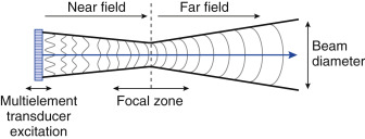
Fig. 1.6 (A) A single-element transducer is made of a synthetic lead–zirconate–titanate ( PZT ) crystal with an internal electrical dipole molecular structure that expands and contracts in thickness mode under a voltage applied to the surfaces via attached electrodes. (B) Grouped transducer elements create a surface to expand and contract in the thickness direction of the transducer crystal to introduce mechanical energy into tissues adjacent to the surface. The surface 7/ vibration and interaction among the individual elements create a collimated beam converging in the near field with a minimum beam diameter at the focal zone depth and, with further travel, diverging into the far field, as shown in Fig. 1.7 . The focal zone depth can be adjusted by introducing brief timing delays of the individual element arrays, as discussed later.
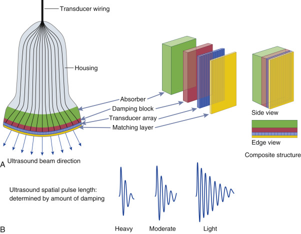
Fig. 1.7 The ultrasound beam from a surface vibration has a A/converging section known as the near field, a diverging B/ section known as the far field, and C/ a focal zone with a minimum beam diameter. In this situation, each transducer element is activated simultaneously. The perspective is looking down on the top edge of the transducer multielement array surface. Ultrasound systems have transducer assemblies of many shapes and sizes composed of an array of PZT elements (typically 64–512) categorized into linear and phased array operation. 8/ Common to all transducers are A/ a protective housing with a shield to prevent electrical interference, B/ an acoustic damping block to shorten the vibrations of the piezoelectric elements, C/ a matching layer to improve the efficiency of ultrasound wave transmission to the skin by reducing acoustic impedance differences, and a material to D/absorb backward-directed ultrasound energy ( Fig. 1.8A ). Fig. 1.8 (A) The transducer is composed of a housing, electrical insulation, and a composite of active element layers, including the PZT crystal, damping block and absorbing material on the backside, and a matching layer on the front side of the multielement array. (B) The ultrasound spatial pulse length is based on the damping material causing a ring-down of the element vibration. For imaging, a pulse of two to three cycles is typical, with a broad-frequency bandwidth, whereas for Doppler transducer elements, less damping provides a narrow-frequency bandwidth. https://radiologykey.com/physics-of-ultrasound-3/
د.كمال سيد Admin
عدد المساهمات : 2461نقاط : 4249السٌّمعَة : 9الجنس : علم بلدك : تاريخ الميلاد : 03/04/1950تاريخ التسجيل : 30/07/2012العمر : 74 الموقع : السودان - سنارالعمل/الترفيه : طبيب عمومى وموجات صوتيةالساعة الان : دعائي :
موضوع: Ultrasound artifacts الجمعة مايو 10, 2024 7:32 am
Ultrasound Artifacts Ultrasound artifacts are commonly encountered and familiarity is necessary to avoid false diagnoses. In some cases, specific artifacts can even offer valuable diagnostic information. For instance, some artifacts may be indicative of certain pathologies. They are not to be confused with ultrasound probe defects, which represent hardware failure.
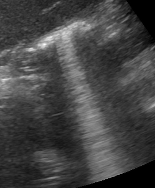
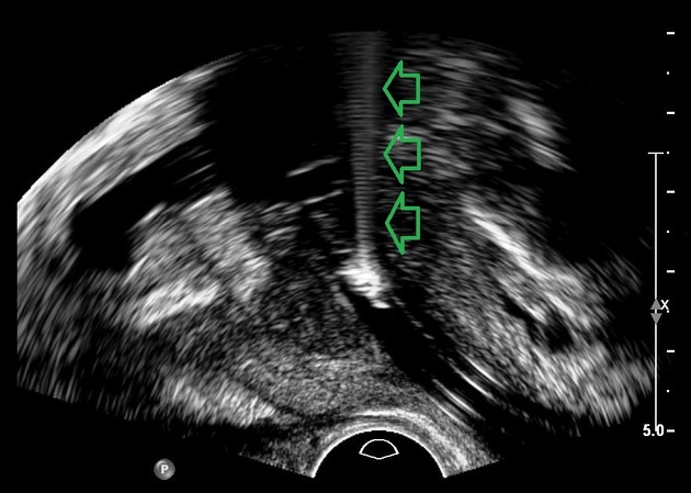
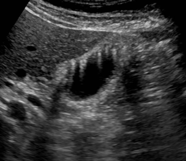
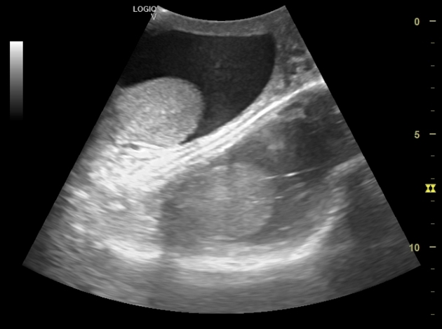
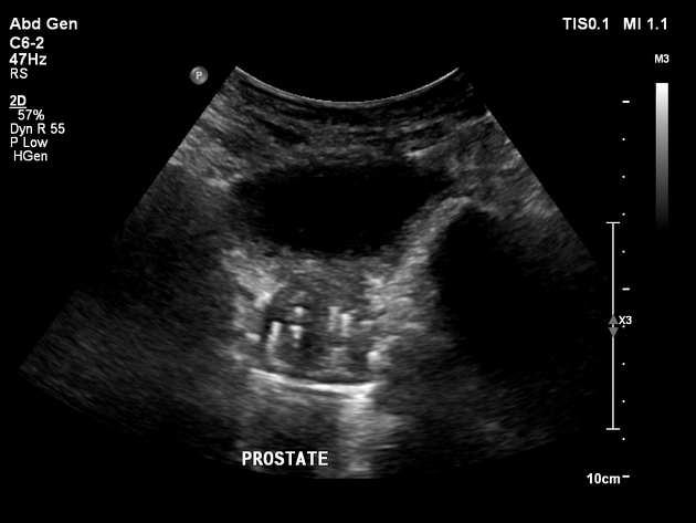
Acoustic enhancement also called posterior enhancement or enhanced through transmission, refers to the increased echoes deep to structures that transmit sound exceptionally well. Acoustic enhancement arises posterior to any lesion that attenuates sound less than the surrounding tissue; the intensity of the transmitted ultrasound beam is relatively preserved distal to the lesion. This is characteristic of fluid-filled structures such as cysts, the urinary bladder and the gallbladder. The fluid only attenuates the sound less than the surrounding tissue. The time gain compensation (TGC) overcompensates through the fluid-filled structure causing deeper tissues to be brighter. Simply it is seen as increased echogenicity (whiteness) posterior to the cystic area. The presence of acoustic enhancement aids in the identification of cystic masses but some solid masses, especially lymphoma, may also show acoustic enhancement posteriorly. hepatic cyst https://radiopaedia.org/articles/acoustic-enhancement?lang=us Cysts and veins are examples of structures that can lead to posterior acoustic enhancement. Because a greater amount of sound waves return to the transducer from tissue with less impendence above it, that tissue generally appears more hyperechoic. A filled urinary bladder allow the ultrasound beam to travel through easily and even increase echoes in the far field. Shadowing and enhancement are useful artifacts for determining the nature of masses. Enhancement results from low attenuation objects in the sound path while shadowing results from strongly reflecting or strongly attenuating objects. epidermal inclusion cyst Acoustic shadowing
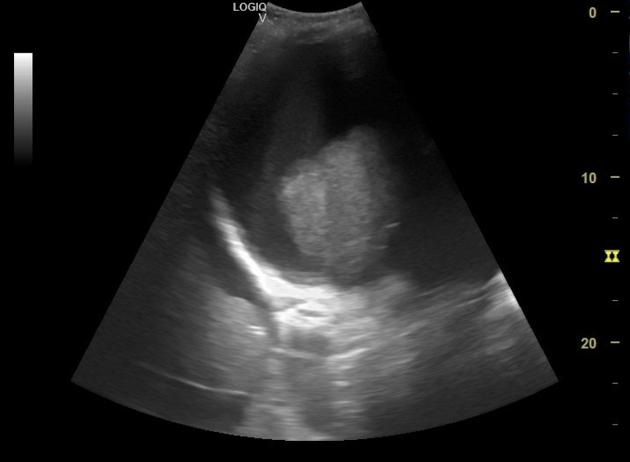
(sometimes referred to as posterior acoustic shadowing) Acoustic shadowingis a form of ultrasoundartifact. It is characterized by the apparent lack of signal deep to an imaged tissue interface, due to all (or nearly all) of the transmitted sound wave being reflected back to the transducer or absorbed by the tissue. It commonly occurs when an area of interest contains a high Z/solid tissue (e.g. calcified gallstone or bone) or at an interface with high acoustic impedance mismatch (e.g. soft tissue/air). Z line : Z-lines define the boundaries of each sarcomere. – The M-line runs down the center of the sarcomere, through the middle of the myosin filaments. – The I-band is the region containing only thin filaments. – The H-zone contains only thick filaments. Acoustic shadow is an ultrasound imaging artifact occurring at boundaries between different tissue impedances, resulting in signal loss and a dark appearance. Acoustic shadowing occurs when objects block the direct sound path between a sound source, and one or more listeners. https://radiopaedia.org/articles/acoustic-shadowing?lang=us
د.كمال سيد Admin
عدد المساهمات : 2461نقاط : 4249السٌّمعَة : 9الجنس : علم بلدك : تاريخ الميلاد : 03/04/1950تاريخ التسجيل : 30/07/2012العمر : 74 الموقع : السودان - سنارالعمل/الترفيه : طبيب عمومى وموجات صوتيةالساعة الان : دعائي :
موضوع: Aliasing phenomenon (ultrasound) الجمعة مايو 10, 2024 12:26 pm
Aliasing phenomenon (ultrasound) Aliasing is a phenomenon inherent to Doppler modalities which utilize intermittent sampling in which an insufficient sampling rateresults in an inability to record direction and velocity accurately
Physics
Unlike continuous wave Doppler (CWD), pulsed wave (PWD) and color flow Doppler (CFD) modalities [alternate between rapid emission of ultrasound waves (at a rate termed the pulse repetition frequency ]PRF]) and reception of incident ultrasound waves]. The time an ultrasound wave travels, given a constant speed in soft tissue (c = 1540 meters/second) will correspond to the distance traveled. Pulsed wave Doppler and color flow Doppler operate on this presumption; when a location of interest is designated, the ultrasound machine will only record returning echoes during an interval that corresponds to the time necessary for wave egress and return [Go Return Time] along a linear path. If [Doppler shifts # occur at a frequency exceeding the maximum pulse interval (1/pulse repetition frequency) detected phase shifts will be calculated based on incorrect assumptions] The Nyquist limitdefines the frequency at which aliasing and range ambiguity will occur, and is equal to thePRF/2. Factors such as @ higher velocities of target structures and @ increasing depth of the region of interest insonated will result in aliasing and consequent range ambiguity {Pulsed Doppler ultrasound (PW) can be used to determine the location of frequency shifts within the cardiac chambers or great vessels. However, it is possible to record similar frequency shifts at sample volume locations distal to their original site; this is referred to as range ambiguity (RA).}. Other potential causative factors include
use of higher frequency transducers
inappropriate angle of insonation
,large sampling volume
Clinical use
Echocardiography A specific use for aliasing in echocardiography is 1/ the calculation of the {EROA} effective regurgitation orifice area in the assessment of valvular regurgitation, most commonly involving the mitral valve. With color Doppler interrogation of a mitral regurgitant jet, a hemispheric flow convergence forms surface area tapering to form the vena contracta before entering the left atrium. The hemispheric area, Proximal Isovelocity Surface Area (PISA) is calculated and the product of PISA and aliasing velocity yields regurgitant flow. The quotient with calculated MR regurgitant VTI yields EROA ..{The Velocity Time Integral (VTI) is a clinical Doppler ultrasound measurement of blood flow, measured by the area under the wave curve and equivalent to the distance traveled by the blood}. . Pulsed wave Doppler In case of spectral Doppler the velocity peak is cut off at the peak of the scale, and the peak is displayed at the bottom of the scale, often overlapping with the rest of the curve. The artifact {Aliasing} can be quickly remedied by 1/ lowering the baseline (if display of flow away from the transducer is not required), or 2/ increasing the PRF. Color flow Doppler In color Doppler aliasing 1/ is encountered as red to blue hues immediately adjacent to each other in a vessel, which is - unlike in case of true flow reversal - not separated by a black region of no flow.2/ The artifact immediately disappears if the upper margin of the velocity scale is increased above the peak flow velocity. Color aliasing 3/ is useful for detecting foci of increased flow (e.g. stenosis, arteriovenous fistula).4/ Note that aliasing does not occur with power Doppler, as it does not display velocity2. Aliasing occurs in color Doppler 5/ when the speed of blood flow exceeds 0.4-0.7m/s6.
عدد المساهمات : 2461نقاط : 4249السٌّمعَة : 9الجنس : علم بلدك : تاريخ الميلاد : 03/04/1950تاريخ التسجيل : 30/07/2012العمر : 74 الموقع : السودان - سنارالعمل/الترفيه : طبيب عمومى وموجات صوتيةالساعة الان : دعائي :
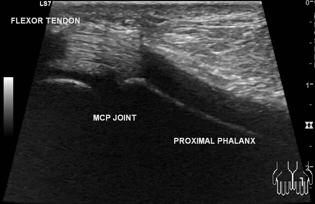
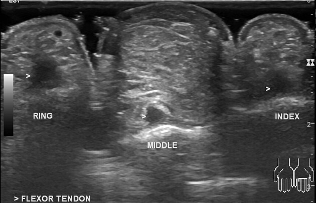
موضوع: Anisotropy/Beam Width US Artifact الجمعة مايو 10, 2024 12:51 pm
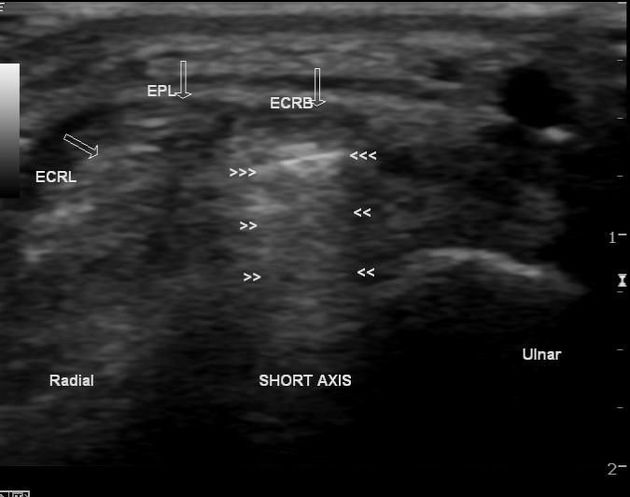
Anisotropy Anisotropy in ultrasound examination is1/an angle-generated artifact. It is produced in2/ tissue that contains multiple, parallel linear sound interfaces (e.g., tendons, ligaments) that lead to3/ the preferential reflection of the beam in one direction. It is encountered in during a {MSK US} musculoskeletal ultrasound, in which, the artifact may prompt an incorrect diagnosis of tendinosis or tendon tear. When the ultrasound beam is incident1/ on a fibrillar structure such as a tendon or a ligament, the organized fibrils may reflect a majority of the insonating sound beam in a direction away from the transducer. When this occurs, the transducer 2/ does not receive the returning echo and assumes that the insonated area should be hypoechoic. This 3/ anisotropic effect is dependent on the angle of the insonating beam.3/ The maximum return echo occurs when the ultrasound beam is perpendicular to the tendon.4/ Decreasing the insonating angle on a normal tendon will cause it to change from brightly hyperechoic (the actual echo from tightly bound tendon fibers) to darkly hypoechoic. If the angle is then increased, the tendon will again appear hyperechoic. If the artifact causes a normal tendon to appear hypoechoic, it may falsely lead to a diagnosis of tendinosis or tear. In some situations, anisotropy may be useful in diagnosis. If a tendon is surrounded by other brightly hyperechoic structures (e.g. fat), then altering the angle of the transducer will cause the tendon to become hypoechoic, differentiating it from the other structures.
UltrasoundBeam Width Artifact
USBeam Width Artifact {BWA} occurs when a reflective objectlocated1/ beyond the widened US beam, after the focal zone, 2/ creates false detectable echoes that are displayed as overlapping the structure of interest. Beam-width artifact refers to the lateral blurring of a point target that occurs as echoes from the same target are insonated at adjacent beam positions. Similarly, if two adjacent point targets are separated by a distance less than the beam width, they will appear as one
Features
To understand this artifact, it is important to remember that the ultrasound beam is not uniform with depth, the main beam leaves the transducer with the same width as it, then narrows as it approaches the =focal-zone&lang=us]focal zone and widens again distal to this zone 1. BWA Usually, it occurs when scanning an anechoic structure and some peripheral echoes are identified, i.e. gas bubbles in the duodenum simulating small gallstones and peripheric echoes in the bladder.
عدد المساهمات : 2461نقاط : 4249السٌّمعَة : 9الجنس : علم بلدك : تاريخ الميلاد : 03/04/1950تاريخ التسجيل : 30/07/2012العمر : 74 الموقع : السودان - سنارالعمل/الترفيه : طبيب عمومى وموجات صوتيةالساعة الان : دعائي :
موضوع: Comet Tail Artifact / Ring Down Artifact الجمعة مايو 10, 2024 4:20 pm
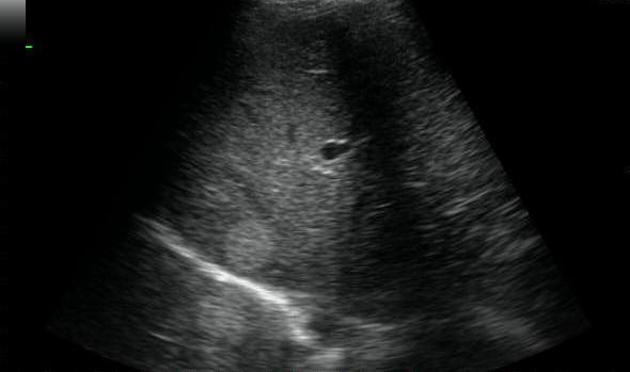
Comet Tail Artifact The comet tail artifact is a grey scale imaging finding seen when small calcific / crystalline / highly reflective objects are interrogated and is believed to be a special form of reverberation artifact It is similar to the color comet tail artifact and is seen in similar situations, although is in general less sensitive than the latter. small renal or ureteric calculi small common bile duct stones adenomyomatosis of the gallbladder pancreatic calcifications of chronic pancreatitis testicular microlithiasis (sometimes) thyroid colloid nodules identification of foreign bodies surgical clips catheter tips debris/glass/metal
Differential diagnosis
Possible considerations include: ring down artifact Echographic examination of the lung surface may reveal multiple "comet-tail images" originating from water-thickened interlobular septa. These images could be useful for noninvasive assessment of interstitial pulmonary edema .. thyroid colloid cyst prostatic brachytherapy seeds Ring-down Artifact" is an Transducer - related artifact that appears as a solid streak or a series of parallel bands radiating away from abdominal gas collections.
The source of Ring-Down Artifact is a small pocket of fluid trapped by surrounding air bubbles
Ring down artifact is a special type of resonance artifact. Its appearance is similar to the ladder-like reverberation of comet-tail artifact, but it is produced by a completely different mechanism. Ring artifact is 1/only associated with gas bubbles, and occurs when an ultrasound pulse encounters2/ a "horn" or "bugle" shaped fluid collection that is trapped between an inverted tetrahedron of 4 bubbles (3 on top and 1 nestled deep to them).3/ The trapped fluid resonates, emitting a continuous signal back to the transducer. Whereas the transducer pulse is broad spectrum, the returning signal consists of one or more discrete (resonant) frequencies. "Beats" between these frequencies4/ produce the variable appearance of the ring down. There is no "reverberation" ( i.e. multiple reflectances). If the sound beam encounters a tetrahedron of bubbles at the correct orientation, then the reverberation created by this structure creates the classic "stepladder" appearance of ring down artifact. stepladder" appearance of ring down artifact colloid nodule thyroid https://radiopaedia.org/articles/ring-down-artifact-1?lang=us
د.كمال سيد Admin
عدد المساهمات : 2461نقاط : 4249السٌّمعَة : 9الجنس : علم بلدك : تاريخ الميلاد : 03/04/1950تاريخ التسجيل : 30/07/2012العمر : 74 الموقع : السودان - سنارالعمل/الترفيه : طبيب عمومى وموجات صوتيةالساعة الان : دعائي :
موضوع: Reverberation Artifact الجمعة مايو 10, 2024 5:50 pm
Reverberation Artifact Reverberation Artifact1/ occurs when an ultrasound beam encounters two strong parallel reflectors When the 2/ ultrasound beam reflects back and forth between the reflectors ("reverberates"), the ultrasound transducer interprets the sound waves returning as deeper structures since it took longer for the wave to return to the transducer. Reverberation artifacts 3/ can be improved by changing the angle of insonation so that reverberation between strong parallel reflectors cannot occur Comet tail artifact4/ is a type of reverberation artifact. This results in a 5/ short train of reverberations from an echogenic focus which has strong parallel reflectors within it (e.g. cholesterol crystals in adenomyomatosis). With comet tail artifact,6/ the space between the two strong parallel reflectors may be less than 1/2 the spatial pulse length, causing the 7/ echoes to be displayed as triangular lines (the later echoes get attenuated and have a decreased amplitude, manifesting on the display as decreased width)
Practical points
Although sometimes grouped with reverberation due to similar appearances, ring down artifact does not arise from the same mechanism and should be considered separately
عدد المساهمات : 2461نقاط : 4249السٌّمعَة : 9الجنس : علم بلدك : تاريخ الميلاد : 03/04/1950تاريخ التسجيل : 30/07/2012العمر : 74 الموقع : السودان - سنارالعمل/الترفيه : طبيب عمومى وموجات صوتيةالساعة الان : دعائي :
موضوع: Mirror image artifact الجمعة مايو 10, 2024 6:18 pm
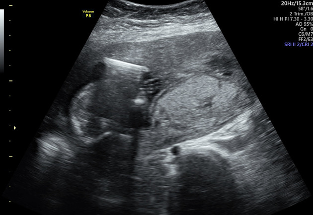
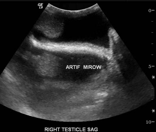
Mirror Image Artifact Mirror image artifact in sonography is seen1/ when there is a highly reflective surface (e.g. diaphragm) in the path of the primary beam. The primary beam2/ reflects from such a surface (e.g. diaphragm) but instead of directly being received by the transducer, 3/ it encounters another structure (e.g. a nodular lesion) in its path and is 4/reflected back to the highly reflective surface (e.g. diaphragm).5/ It then again reflects back towards the transducer. The ultrasound machine 6/ makes a false assumption that the A/ returning echo has been reflected once and hence the 7/ delayed echoes are judged as if being returned from a deeper structure, thus giving a mirror artifact on the other side of the reflective surface. It is a friendly artifact that 8/ allows the sonographer to exclude pleural effusionby the reflection of the liver image through the diaphragm. 9/Examples: reflection of a A/ liver lesion into the thorax (the commonest example) reflection of B/ abdominal ascites mimicking pleural effusion duplication of C/ gestational sac (either ghost twin or heterotopic pregnancy) duplication of the D/ uterus To avoid this artifact, 10/ change the position and angle of scanning to change the angle of insonation of the primary ultrasound beam.
عدد المساهمات : 2461نقاط : 4249السٌّمعَة : 9الجنس : علم بلدك : تاريخ الميلاد : 03/04/1950تاريخ التسجيل : 30/07/2012العمر : 74 الموقع : السودان - سنارالعمل/الترفيه : طبيب عمومى وموجات صوتيةالساعة الان : دعائي :
موضوع: Side lobe artifacts/Speckle artifact السبت مايو 11, 2024 7:36 am
Side Lobe Artifact Side lobe artifacts occur1/ where side lobes reflect sound from a strong reflector that is outside of the central beam, and where the 2/ echoes are displayed as if they originated from within the central beam. Strong reflectors include3/ bowel gas adjacent to the gallbladder or urinary bladder Ultrasound transducer crystals expand and contract to produce primary ultrasound beams in the direction of expansion and contraction. 4/Secondary beams occur because the crystals also expand and contract radially. These radial beams are called side lobe beams. 5/ Side lobe beams are low-intensity beams 6/ that surround the central beam. Side lobe artifacts are 7/ echogenic, linear or curvilinear artifacts. Side lobes are an unwanted ultrasound artifact originating from the finite-sized ultrasound transducer aperture. 8/These artifacts increase noise and reduce image contrast. You can 9/reduce the effects of the artifact by A/ decreasing the transducer's frequency,B/ decreasing depth, and C/choosing an anatomic structure with a velocity below the Nyquist limit.
Speckle artifact Speckle artifact may be encountered in ultrasound. 1/It is caused by the scattering of waves from the surface of small structures within a certain tissue. 2/The artifact produces a textured appearance. Speckle is 3/ the random granular texture that obscures anatomy in ultrasound images and is usually described as “noise”. 4/ Speckle is created by a complex interference of ultrasound echoes made by reflectors spaced closer together than the ultrasound system's resolution limit. https://radiopaedia.org/articles/speckle-artifact-1?lang=us


 الجمعة أبريل 19, 2024 8:26 pm
 (2.1)
(2.1) (2.2)
(2.2)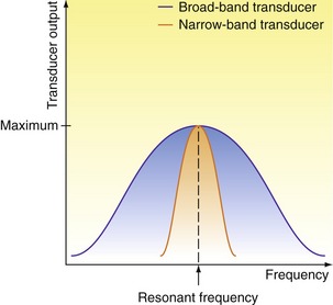
 (2.3)
(2.3)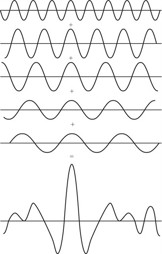
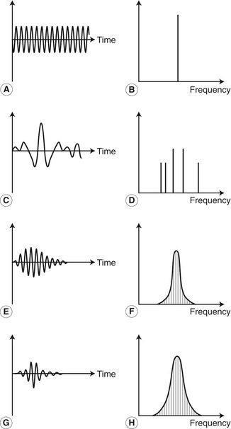
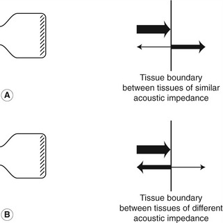

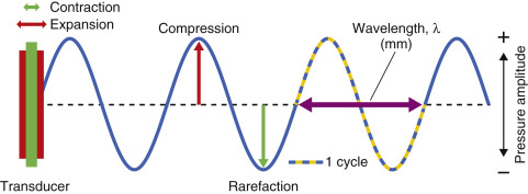
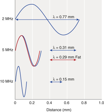

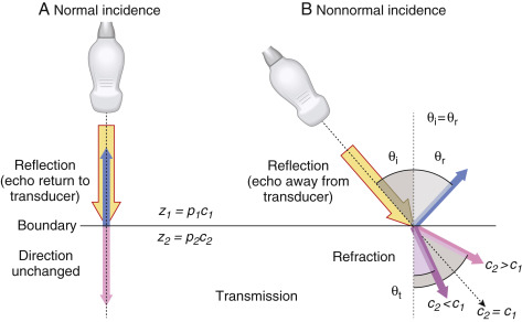 Fig. 1.3
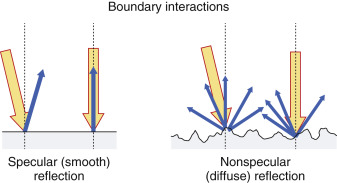


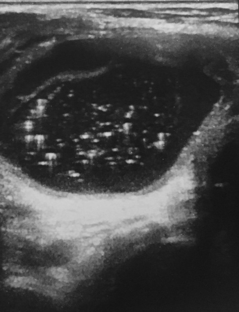

 colloid nodule thyroid